Safe Isolation
Local or international regulation require those in control of part or all of an electrical system to ensure that it is safe to use and that it is maintained in a safe condition.
Unsuitable test probes, leads, lamps, voltage indicators and multimeters have caused arcs due to:
- Inadequately insulated test probes (typically having an excessive length of bare metal at the contact end) accidentally bridging a live conductor and adjacent earthed metalwork; or
- Excessive current drawn through test probes, leads and measuring instruments.
This happens when a multimeter is set to the wrong function, e.g. set on a current or resistance range when measuring voltage.
Other causes of accidents which could lead to electric shock are:
- Inadequate insulation of test leads and probes;
- Exposed live terminations at instruments and indicators;
- A lead falling off one of the terminals of a meter and either the meter terminal or the lead terminal remaining live;
- Incorrect use of test equipment, e.g. a multimeter applied to conductors at a voltage which exceeds the maximum working voltage of the instrument;
- Use of poorly constructed makeshift test equipment, eg a test lamp consisting of a combination of a bayonet lamp holder, bulb and two single insulated conductors with bared ends;
The use of long intertwined leads which were not easily distinguished, resulting in one lead being connected across the instrument and the other short circuiting the live conductors under test.
VOLTAGE DETECTION INSTRUMENTS
Instruments used solely for detecting voltage fall into two categories. These are:
- Detectors which rely on an illuminated bulb (test lamp)
- Meter scale (test meter).
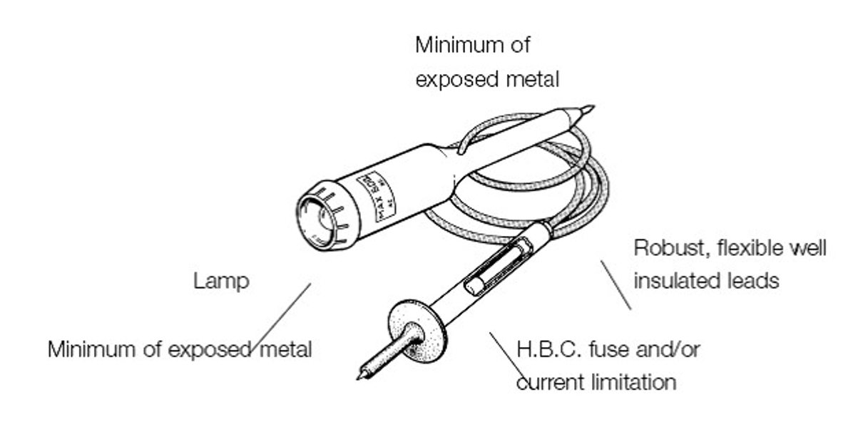
Test lamps fitted with glass bulbs should not give rise to danger if the bulb is broken. It may be protected by a guard.
These detectors require protection against excess current. This may be provided by a suitable high breaking capacity (hbc or hrc) fuse or fuses, with a low current rating (usually not exceeding 500 mA), or by means of a current-limiting resistor and a fuse. These protective devices are housed in the probes themselves. The test lead or leads are held captive and sealed into the body of the voltage detector.
Detectors which use two or more independent indicating systems (one of which may be audible) and limit energy input to the detector by the circuitry used. An example is a 2-pole voltage detector, ie a detector unit with an integral test probe, an interconnecting lead and a second test probe.
These detectors are designed and constructed to limit the current and energy which can flow into the detector. The limitation is usually provided by a combination of circuit design, using the concept of protective impedance, and current limiting resistors built into the test probes. These detectors are provided with in-built test features to check the functioning of the detector before and after use. The interconnecting lead and second test probe are not detachable components.
Test lamps and voltage indicators are recommended to be clearly marked with:
The maximum voltage which may be tested by the device; and
Any short time rating for the device if applicable. This rating is the recommended maximum current which should pass through the device for a few seconds. These devices are generally not designed to be connected for more than a few seconds.
PRECAUTIONS BEFORE TESTING
Before testing begins it is essential to establish that the test device including all leads, probes and connectors is suitably rated for the voltages and currents which may be present on the system under test.
Before any testing is carried out ensure that:
The equipment which is to be worked on is safe for the intended tests; and
The working environment does not present additional dangers. These dangers include:
Inadequate space to work safely; An insecure footing;
Insufficient light;
Potentially flammable gases or vapours; Explosive or conductive dusts.
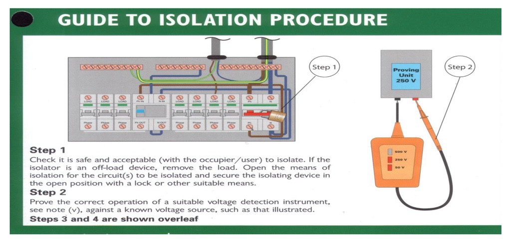
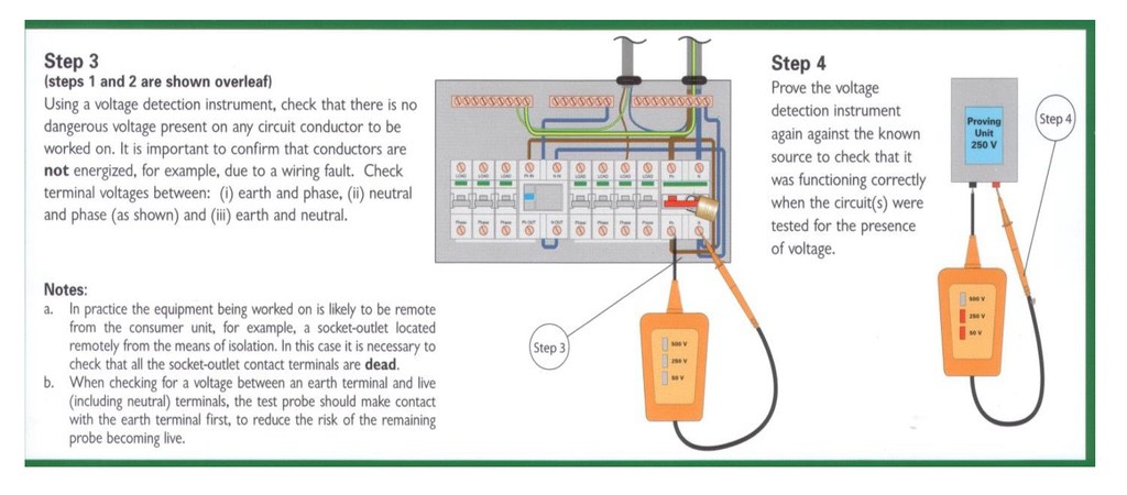
Where a test is being made simply to establish the presence or absence of voltage, the preferred method is to use a proprietary test lamp or 2-pole voltage detector suitable for the working voltage of the system rather than a multimeter. Accident history has shown that the use of incorrectly set multimeters or makeshift devices for voltage detection has often caused accidents.
NOTE: Test lamps and some voltage indicators may fail to danger, eg a faulty lamp not indicating a live circuit. These devices should be proved before and after use on a known live source of similar voltage to the circuit under test, or alternatively on a portable test source.